Constructing Syntax Diagrams
Inserting Elements
|
The
segments below reflect the result of inserting new elements as represented by
entries 1-6. To insert an element left click on the desired one. (Do not drag
it. Dragging on the backplane will cause the diagram to move.) After having
clicked on an element in the panel, the cursor will change to the element
symbol.
|
|
|
||
|
|
|
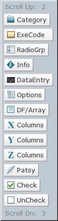
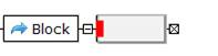
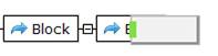
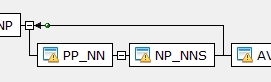
Before contacting an element edge or center. When the attachment point turns red or green, a left mouse click will cause it to attach or replace at that point. |
||
|
1 |
|
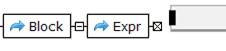
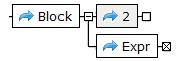
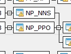
Right contact leads to the element being attached to the right side. If there were already elements to the right, the new one would be inserted between.
|
||
|
2 |
|
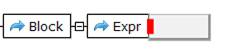
Top contact leads to the element being connected to the left side and placed above. Any already above would be pushed up.
|
||
|
3 |
|
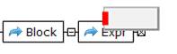
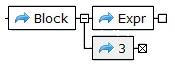
Bottom contact leads to the element being connected to the left side and placed below. Any already below would be pushed down.
|
||
|
4 |
|
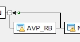
Left contact leads to the element being inserted to the left side, between the current and previous elements.
|
||
|
5 |
|
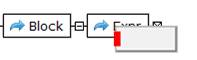
Center contact leads to the new element replacing the current element.
|
||
|
6 |
|
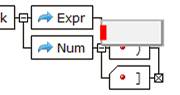
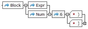
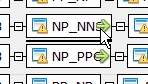
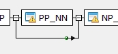
Contacting a vertical connection will also cause the attachment point to turn red. If the mouse is clicked at this point the new element will be inserted after the join portion of the vertical and before any forks.
|
||
Junctions
The
junction boxes between or at the end of elements will contain one of four
different symbols; a minus (![]() ),
a plus (
),
a plus (![]() ),
an X (
),
an X (![]() ),
and a blank (
),
and a blank (![]() ).
If there is a minus and the box is click on, it will change to a plus and cause
all of the following elements to disappear. Clicking on a plus will reverse the
condition. The boxes with an X behave as those with a minus but also indicate a
stop. Any element that is activated will continue to the next element unless
the element’s execution fails or a stop is encountered. Blank boxes as with
execution failure cause backtracking to find an alternate solution.
).
If there is a minus and the box is click on, it will change to a plus and cause
all of the following elements to disappear. Clicking on a plus will reverse the
condition. The boxes with an X behave as those with a minus but also indicate a
stop. Any element that is activated will continue to the next element unless
the element’s execution fails or a stop is encountered. Blank boxes as with
execution failure cause backtracking to find an alternate solution.
The junction spheres located along columns of elements can be one of three different colors. Green spheres represent junctions of outputs; i.e. joins. Red represents alternative choices. Blue represents must execute element connections; i.e. forks.
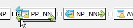
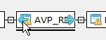
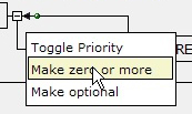
Left clicking on an element icon will activate the wiring mode. In this mode the cursor changes to a cross-hair and arrows appear on the original element and each element pass over. Left clicking on an arrow, either the original or others will be joined together. When arrows of different colors are at the same end of an element, the arrows of the same color are always joined together. When necessary, directional elements representing else or repeat will automatically be inserted. In the case of syntax diagrams, repeats can be converted from “repeat one or more times” to repeat zero or more times”.
|
Before |
After |
|
|
|
|
|
|
|
|
|
|
|
|
|
|
|
|
Right click when the cursor is on terminal element will produce a menu with the following operations. |
|
Operation |
Description |
|
Toggle Hex Format
|
Atomic elements can accept a values represented by a hexadecimal number. Pressing the right button of the mouse, and then selecting this entry will cause the entered hex value to represent the terminal value and display a capital X or H superscript in the upper right corner.
These two atoms do not represent the same value. The second of the two is looking for a literal match with all six characters, “0x2345”. The first is looking for a match to the value composed of two 8-bit characters; the first with the hex value “0x45” and the second with the hex value “023”. (The “0x” is optional.) |
|
Toggle Case Sensitive |
An atomic ASCII element can be made Case Insensitive by placing the cursor on it, pressing the right button of the mouse, and then selecting this entry. Repeating this action will toggle it back to case sensitive. When the atom is insensitive to case, a capital “I” will be displayed in the upper right corner of the element.
The atom with the I superscript will consume (match) any combination of upper and lower case character of the word “rand” for example “rANd”, where as, the other only matches a precise copy. |
Repeat Operations
|
Operation |
Description |
|
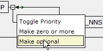
Toggle Priority |
Used for defining loopback, the .repeat’s priority can be set with the “Toggle Priority” entry in its options menu. It will toggle back and forth between high and low. Priority is generally not an issue, but as in the example below, the “A” path would never be taken.
Unless the priority of .repeat was changes to low as indicated by the “L” subscript instead of the “H”.
Neither “H” nor “L” is displayed for loops that represent “zero or more” repetitions.
|
Precedence
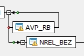
Unlike conventional syntax diagrams, these elements have precedence with the top-most having the highest priority. This makes it very convenient for creating rules by using exceptions as illustrated below.
|
|
|
|

In EBNF this would be: rule ::= “G” {<all characters except H>}* “H” ; which can be difficult to implement. Precedence can not be represented in EBNF and therefore should be saved in the SQXL XML format to avoid losing the descriptive information. This also means that with options such as those to the right where one is the complete leading subset of another, the longer should be above the shorter.
Junctions
The
junction boxes between or at the end of elements will contain one of four
different symbols; a minus (![]() ),
a plus (
),
a plus (![]() ),
an X (
),
an X (![]() ),
and a blank (
),
and a blank (![]() ).
If there is a minus and the box is click on, it will change to a plus and cause
all of the following elements to disappear. Clicking on a plus will reverse the
condition. The boxes with an X behave as those with a minus but also indicate a
stop. Any element that is activated will continue to the next element unless
the element’s execution fails or a stop is encountered. Blank boxes as with
execution failure cause backtracking to find an alternate solution.
).
If there is a minus and the box is click on, it will change to a plus and cause
all of the following elements to disappear. Clicking on a plus will reverse the
condition. The boxes with an X behave as those with a minus but also indicate a
stop. Any element that is activated will continue to the next element unless
the element’s execution fails or a stop is encountered. Blank boxes as with
execution failure cause backtracking to find an alternate solution.
The junction spheres located along columns of elements can be one of three different colors. Green spheres represent junctions of outputs; i.e. joins. Red represents alternative choices. Blue represents must execute element connections; i.e. forks.
Element Superscripts & Subscripts
|
Superscripts |
Element Flag Description |
|
$ |
Only present following a parser build (Compile Rule). Indicates that this element has the possibility of generating an output term in the postfix results. If the element has a name, it is used as a default value. Otherwise, a unique one should be entered into the formula if it is to be recognized by the parser. (If two such elements have the same name, one should be changed.) |
|
X,H |
In the case of an Atom/Terminal element indicates the hexadecimal value should represent the contents and not the lateral. |
|
I |
In the case of an Atom/Terminal element the contents should be interpreted as case insensitive. Refer to Syntax Diagram Elements for details. |
|
H |
In the case of a Repeat element refer to Syntax Diagram Elements for details. |
|
L |
In the case of a Repeat element refer to Syntax Diagram Elements for details. |
|
R |
Indicates the term/element is part of a direct or indirect recursion. |
|
M |
Indicates more than one rule has the same name |
|
Right click when the cursor is on rule head will produce a menu with the following operations. Notice that all the elements of the selected rule are lit indicating that the operation could effect any or all of them. |
|
Operation |
Description |
|
Run Emulation |
Once a parser rule set has been built, test rules can be run and traced to determine if the grammar is performing as expected. Selecting the entry will cause that to happen. |
|
Compile Rule Set |
Build a parser image for the rule set whose root is this rule. Algorithms compute the states required to implement the grammar, which are then added to the diagram. A $ will appear on elements that have the possibility of generating an output term in intermediate postfix results. If the element has a name, that be used as a default value. Otherwise, a unique one should be entered into the formula if it is to be recognized by the parser. |
|
Convert to EBNF |
This operation will convert all the selected rules to an EBNF representation and display it in the Trace window. Syntax diagrams can be converted to their equivalent EBNF representation for feeding numerous third party compilers. Generally, some modification or augmentation to the EBNF output is required to have it conform to each compiler’s unique specifications. |
|
Remove Direct Recursion |
This operation removes left recursive terms that are found in the selected rules. After this operation, running a reduce operation may provide a cleaner looking presentation. (RecursiveRules.xml has a collection of recursive rules for practice) |
|
Reduce w/o Precedence |
This operation combines terms where possible and reformats the rule to have a left to right, top down form. |
|
Reduce with Precedence |
Same as above but does not make any changes that would disrupt the process order of terms. |